

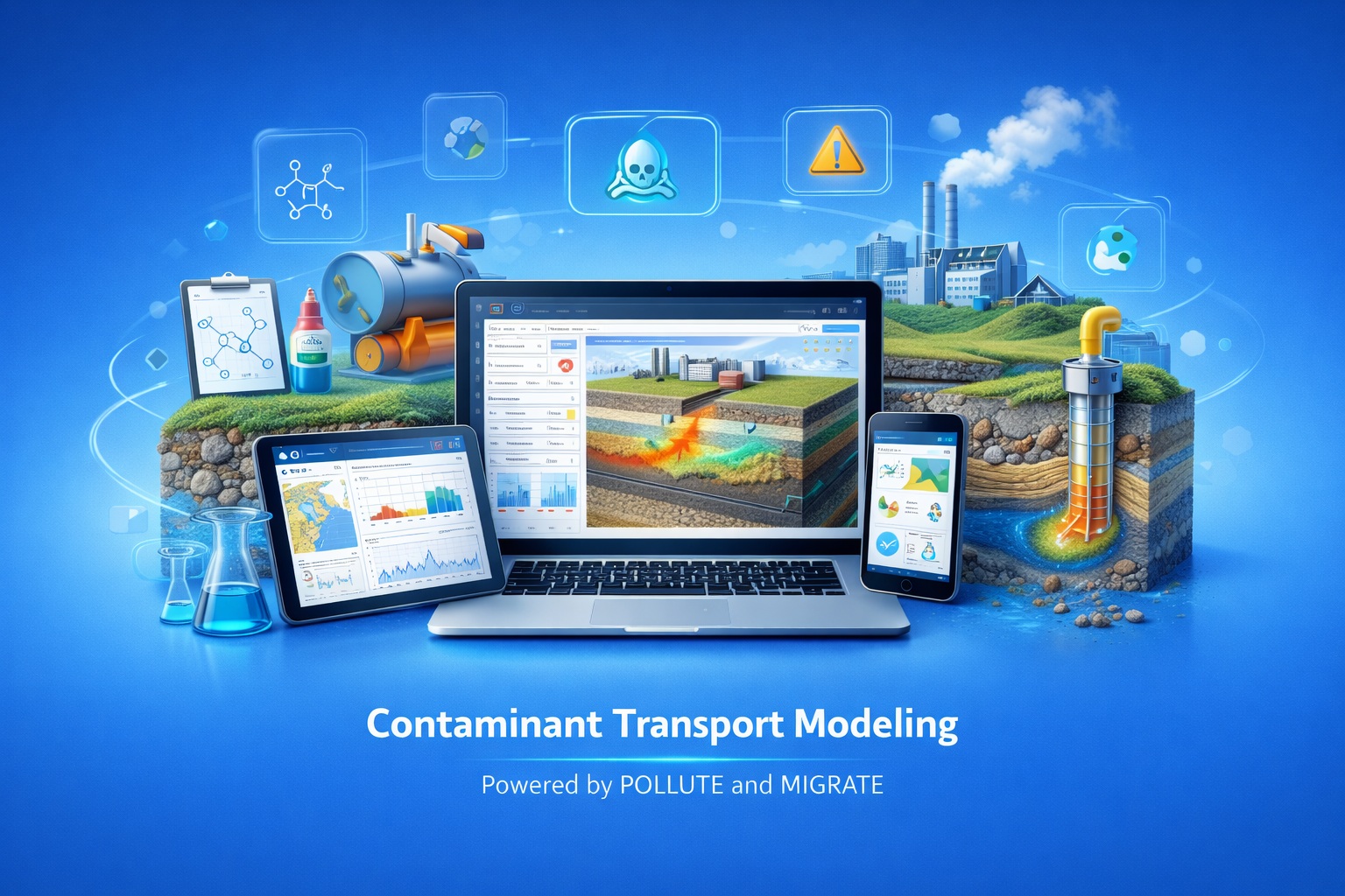
Define Layered Systems and Evaluate Contaminant Transport
Build 1D and 1.5D analytical models of contaminants moving through natural soils, groundwater systems and engineered barriers.
Configure model layers and boundary conditions, calculate concentration, flux and mass results, compare scenarios and export the supporting output for technical review.
Review the Core Modeling Workflow
Move directly to the part of the model definition or results workflow that matters to your evaluation.
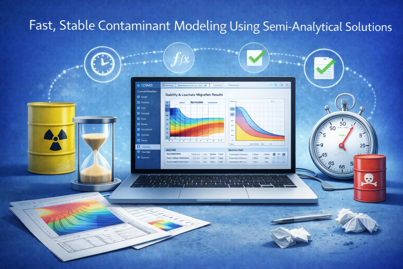
Fast Scenario Evaluation without a Numerical Grid
POLLUTEv10 applies analytical solutions to the advection–dispersion equation for vertically layered systems. The approach supports rapid recalculation during design comparison, sensitivity review and long-term performance assessment.
- Represent the vertical transport path as a sequence of layers
- Define the source, material properties and lower boundary
- Calculate results at selected depths and times
- Compare design alternatives and parameter assumptions
- Preserve the model setup with its graphs and tabular output
The Essential Tools for Building and Reviewing a Model
These capabilities form the foundation of POLLUTEv10 before optional or advanced special-feature configurations are considered.
Unlimited Model Layers
Construct the vertical profile from the number of material and barrier layers required by the conceptual model.
Layer-Specific Properties
Assign applicable thickness, porosity, hydraulic conductivity and dispersive transport properties by layer.
Source Definition
Represent a constant concentration or a finite-mass source according to the selected model configuration.
Lower Boundaries
Select a fixed concentration, zero-flux condition or passive sink to represent the receptor at depth.
Landfill Templates
Use supplied starting configurations for common landfill and liner-system model types.
Professional Results
Present concentration against time, concentration against depth, flux, mass and supporting tables.
Rapid Recalculation
Update assumptions and compare scenarios without a time-marching numerical workflow.
Excel Export
Transfer calculated tables for additional review, custom presentation and engineering reports.
Reusable Models
Save project models and use appropriate configurations as the basis for related scenarios.
Represent Engineered Barriers and Natural Strata Together
Each layer describes a distinct part of the contaminant transport path. The model can combine geomembranes, compacted clay, drainage materials, native soils, aquitards and aquifers according to the project conceptual model.
- Keep units consistent throughout the model
- Use values supported by project data or documented references
- Separate materially different zones into appropriate layers
- Record the basis and uncertainty for influential parameters
Select Boundary Conditions That Match the Conceptual Model
The upper and lower boundaries determine how contaminant mass enters the profile and how the model represents conditions at depth.
| Boundary | Option | Typical Interpretation | Review Question |
|---|---|---|---|
| Upper source | Constant concentration | Source concentration is maintained for the modeled condition. | Is a sustained source consistent with the facility and assessment period? |
| Upper source | Finite mass | Available contaminant mass can diminish as the source is depleted. | Are source volume, mass and concentration assumptions supported? |
| Lower boundary | Fixed concentration | The concentration at the lower boundary is prescribed. | What measured or conceptual condition supports the selected value? |
| Lower boundary | Zero flux | No contaminant mass crosses the specified lower boundary. | Is an impermeable or symmetry condition defensible? |
| Lower boundary | Passive sink | An aquifer or receptor removes mass reaching the lower boundary. | Do the receptor assumptions represent the groundwater system? |
Start with a Template, Then Make It Project-Specific
Supplied templates can establish representative layer sequences and model structure for common landfill configurations. They are starting points—not substitutes for site-specific design information.
- Select the template closest to the actual barrier system
- Confirm every layer, material and dimension
- Replace default values with project-supported parameters
- Review source and lower-boundary assumptions
- Save the verified configuration for related scenarios
Representative Starting Configurations
- Primary liner landfill
- Primary and secondary liner system
- Vertical migration model
- Horizontal migration model
- User-created reusable templates
Available templates and fields should be confirmed in the current installed version during evaluation.
Review More Than One Measure of Model Performance
Use complementary result views to understand when, where and how contaminant mass moves through the modeled system.
Concentration vs. Time
Track predicted concentration at a selected depth or receptor through the assessment period.
Depth Profiles
Inspect the concentration gradient through the modeled profile at selected times.
Flux and Mass
Evaluate contaminant transfer and cumulative mass in addition to concentration.
Tables and Excel
Review numerical results and export applicable data for reporting or additional analysis.
Keep the Calculation Connected to Its Engineering Basis
A repeatable workflow makes it easier to review assumptions, reproduce scenarios and explain the final prediction.
Define the Question
Identify the receptor, contaminant, design case and assessment period.
Build the Profile
Enter the natural strata and engineered barrier layers.
Set Boundaries
Configure source behavior and the lower receptor condition.
Enter Parameters
Use consistent units and documented project values.
Calculate and Test
Run the baseline and evaluate influential assumptions.
Review and Report
Check graphs, tables, mass balance context and conclusions.
Apply POLLUTEv10 Where a Layered Analytical Model Fits
The suitability of the formulation and assumptions should be confirmed for each site and decision.
Landfill Assessment
Evaluate contaminant migration through landfill cover and liner systems.
Barrier Performance
Compare layered containment designs and material assumptions.
Groundwater Impact
Estimate concentrations, flux and mass reaching a defined receptor.
Design and Regulatory Review
Document scenarios used to support an engineering assessment or submission.
Evaluate POLLUTEv10 with a Representative Project
Confirm the core model, outputs and product boundary against the work your organization actually performs.
- Can the site be represented by the available 1D or 1.5D formulation?
- Are the required source and lower-boundary conditions supported?
- Can every natural and engineered layer be represented appropriately?
- Are the needed concentration, flux, mass and profile outputs available?
- Can the model assumptions and results be reviewed efficiently?
- Do Excel export and report handoffs meet the project workflow?
- Are advanced special features required beyond this core scope?
- What migration, training, maintenance and licensing support is needed?
Recommended Evaluation Path
- Define one representative assessment question.
- Build its verified layer sequence.
- Check boundary-condition support.
- Run a baseline and alternative scenario.
- Review graphs, profiles, flux and mass.
- Export results and test the report handoff.
Continue from Product Evaluation to Technical Detail
Use the Knowledge Center and product resources to examine advanced capabilities, landfill design context and example applications.
POLLUTEv10 Core Features Guide
Read the explanatory article covering layer properties, boundaries, templates and output.
Read the Core Features guidePOLLUTE Special Features
Review advanced configurations that extend the core model for specialized conditions.
Explore Special FeaturesPOLLUTE Examples
Inspect representative models and the engineering questions they evaluate.
Browse POLLUTE examplesContaminant Modeling Guide
Understand the broader landfill-design and groundwater-protection workflow.
Read the complete guidePOLLUTE and MIGRATE Upgrade
Review version 10 modernization, compatibility and migration considerations.
Review the upgrade overviewResearch Paper Viewer
Access technical background reports related to contaminant migration and barrier performance.
Download the free viewerReady to Evaluate POLLUTEv10?
Build a representative layered model, test the required boundaries and review the outputs used in your engineering decisions.